Getting PCB Heating Right (Without the Guesswork)
Most shops just try to get the board hot and call it a day. But if you’ve been doing this a while, you know it’s not that simple. It’s all about the gap between the solder mask and the component body. If that temperature swings by even five degrees, you’re looking at delamination or those annoying cold solder joints. Not a great way to start your morning.
How the Tech Actually Works
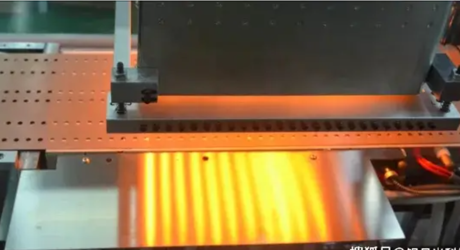
We use closed-loop PID controllers to keep a handle on the heat. Now, this isn’t just about picking a number on a screen. It’s about the climb—the ramp-up. A digital station adjusts the wattage on the fly so you don’t overshoot your target. We spend a lot of time tweaking air velocity and infrared intensity. Why? Because we want the heat to soak deep into the PCB layers without scorching the top. It’s the difference between a slow braise and burning the outside of your steak.
The Hardware Trade-off
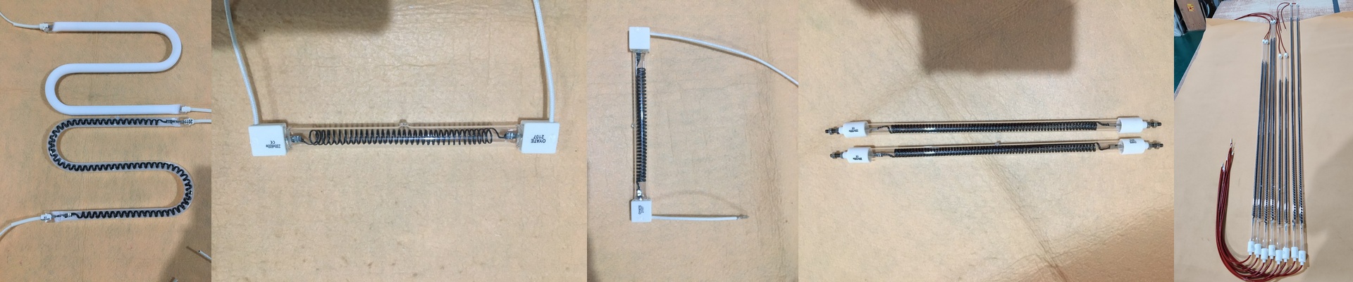
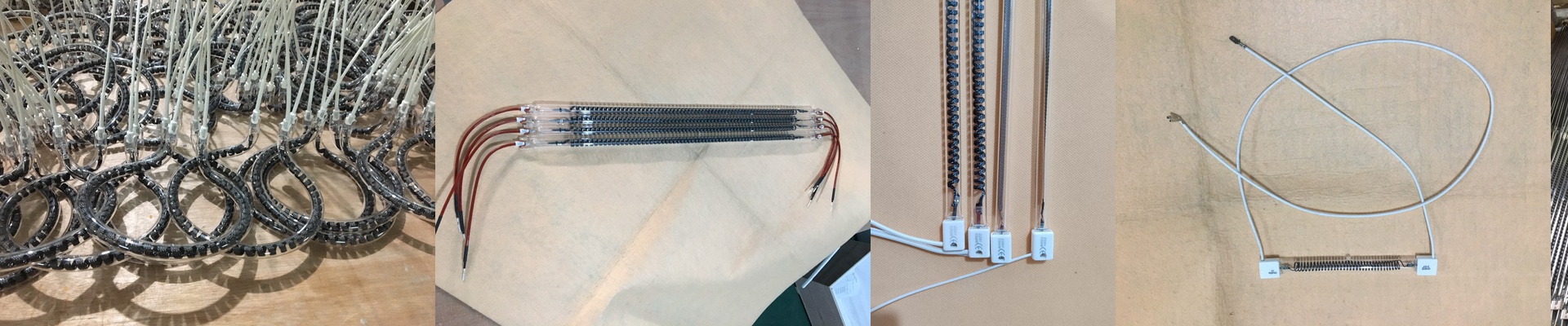
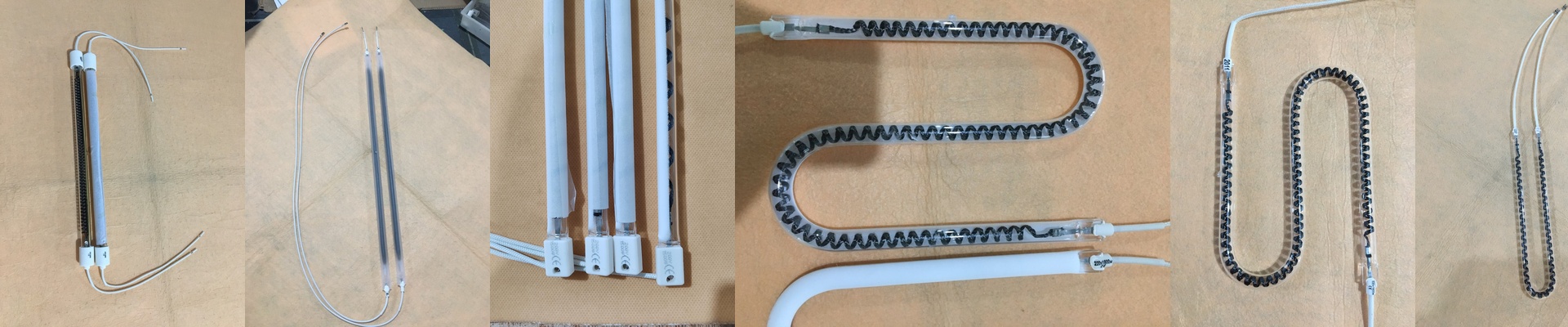
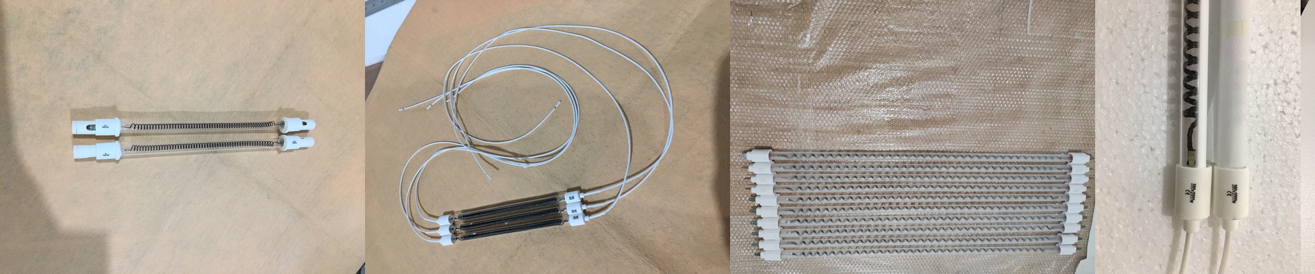
We went with high-density heating elements to keep the footprint small. It saves space on your bench and gives you a much faster response time. But here’s the catch: high-wattage density means the elements can wear out faster if you’re pinning them at 100% all day. To keep things running smooth, we suggest giving your power supply about 20% overhead. It keeps the components from stressing out.
Making it Work in Your Shop
You don’t want a project; you want a tool. That’s why these are designed to drop right into where your old analog gear used to be. We used standard connectors and digital interfaces, so you can wire it up and start profiling in a few minutes. The real win here is repeatability. Whether you’re tinkering with one prototype or pushing through a batch of a thousand, the heat should feel exactly the same every time. We track the distribution across the whole board to kill off any dead zones. No more guessing. No more “hoping” the center of the board got hot enough. Just a clean reflow.